This is a post about designing and building my own custom split keyboard. If you
are interested in the Ergogen/KiCad/gerber/firmware files, check out the
releases page on GitHub.
Motivation
A few years ago, I ventured into the rabbit hole of custom mechanical keyboards
and built my first one: the
KBD75 v3.
(Technically, my first build was the Atreus
about ten years ago, but I never ended up using it on a daily basis. So, I don't
count that.) I was satisfied with my KBD75, but occasionally, I found myself
curious about split keyboards due to their many
benefits. After much consideration,
I finally decided to try out the Lily58,
which seemed to be a very popular choice. I didn't want to go too minimal with a
layout like the Corne or
Kyria, since I could always
experiment with a smaller layout by disabling unnecessary keys. I ended up
purchasing the Aurora Lily58 kit
from splitkb. My main reason was that the PCB supported both encoders and
regular switches on the inner side (see the picture below). At that time, I
wasn't sure which I would prefer. I assumed it would be the switches, but I was
fundamentally wrong.
I used the Lily58 as my daily driver for about six months, and I was pleasantly
surprised. The ability to splay the keyboard was a natural fit for my wrists.
However, I wasn't completely satisfied with the physical layout; for instance,
the two outermost columns weren't perfectly aligned for my pinkies. Another
issue was the location of the thumb cluster. The two innermost keys were
difficult to reach for my thumb because they were positioned under the palm.
Additionally, the thumb cluster was arranged almost in a straight line, which
was unnatural. I would have preferred a more curved thumb cluster, similar to
what the Kyria keyboard has.
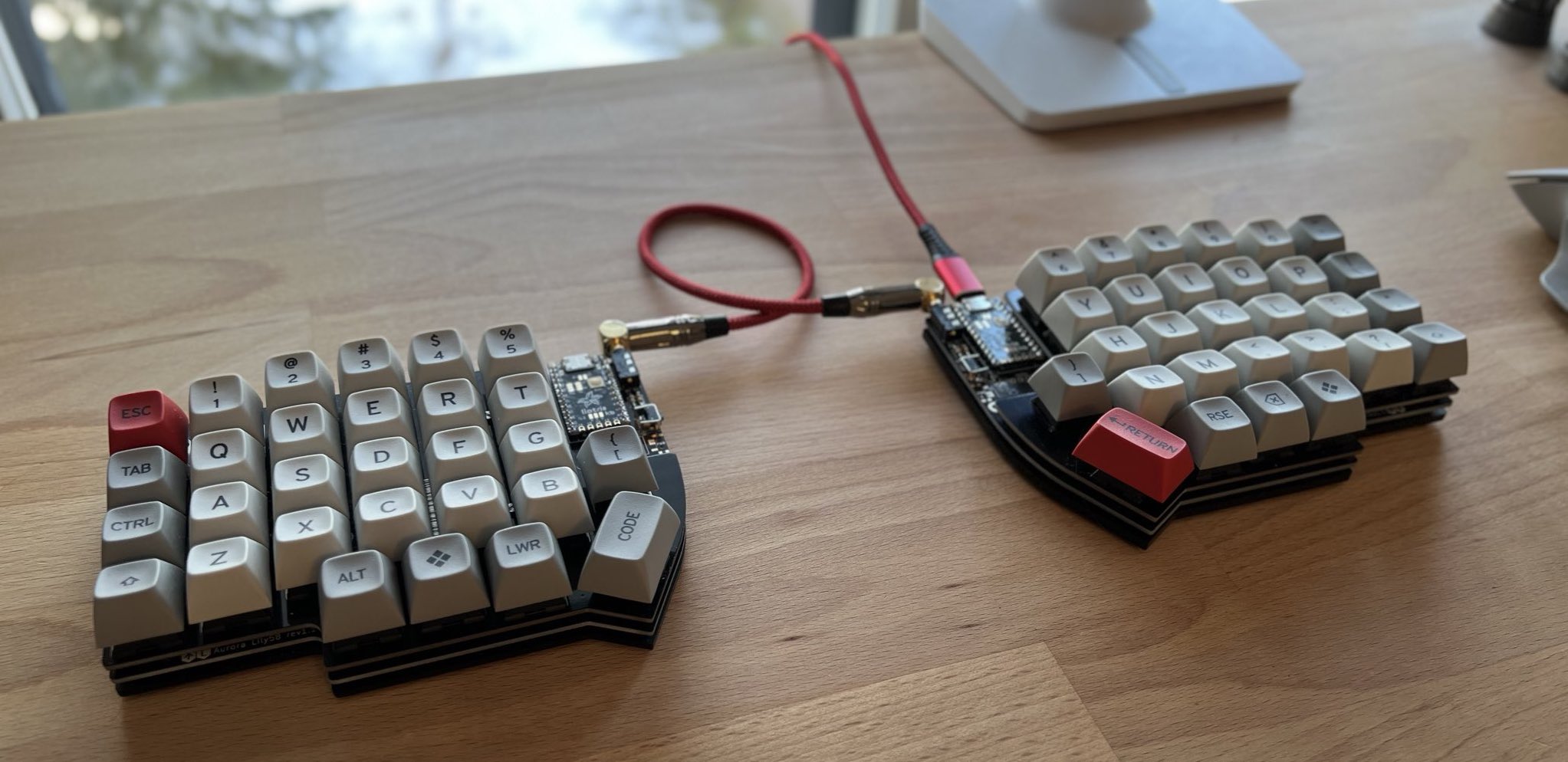 The well-served Lily58.
The number of switches felt right. Even though I didn't find much use for the
top row (the number row), I still prefer a higher switch count over relying
heavily on too many layers. Therefore, the 4x6+4 layout was a good fit for me.
As mentioned earlier, I found the two extra keys near the inside edge
inconvenient to use, and therefore, I will give encoders a chance next.
The Sofle v2, another very
popular split keyboard, solves some of these issues, but I began to wonder how
hard it could be to design my own keyboard — one that would be the perfect fit
for my fingers and needs. It turns out it wasn't too difficult.
Design Goals and Principles
I set down a few goals and principles for my new keyboard:
- Based on Lily58 and Sofle — The column positions are optimized for my
fingers rather than designing something entirely new. We'll stand on the
shoulders of giants.
- Keep It Simple and Stupid
(KISS) — This mainly means:
- No (RGB) LEDs or displays — I don't need them.
- No wireless — I have a pile of laptops on my desk and prefer using a
KVM switch rather than deal with
Bluetooth.
- No reversible PCBs — While this will slightly increase the cost, my OCD
can't handle that mess.
- Parametric design — There will naturally be many iterations, and I want to
avoid bugs caused by not updating something consistently.
- Avoid overly exotic layouts/key mappings — This won't be my only input
device, and I'll still use a standard QWERTY keyboard occasionally, like on my
laptop. So, I'd rather not introduce too much switching overhead.
- Easy access to both Ctrl and ⌘ keys — I use a mixture of different
operating systems and VMs.
Proof of Concept
Where would you start with your personal keyboard layout? There's a tool called
Ergopad that allows you to use an iPad to get a
rough idea of the optimal layout for you. However, I wanted to get a more
realistic feel for my design, so I ended up creating a 3D-printed rig to test
different layouts.
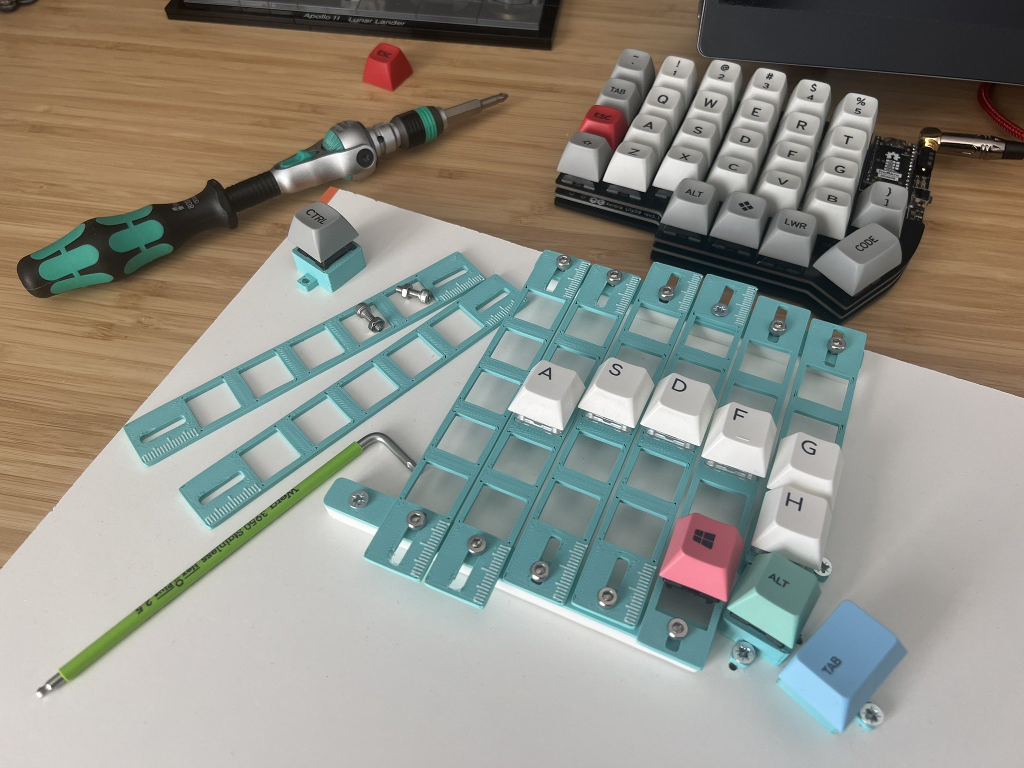 The custom split
keyboard rig.
With this rig, I could easily iterate over different column offsets, make small
adjustments, physically press the keys, and repeat the process until I found the
perfect layout for my fingers. This hands-on approach was one of the best
aspects of the design process. I initially thought that adding a measurement
scale to the key plate sticks was a brilliant idea, but I still found myself
measuring each offset with a caliper to get the most accurate measurements.
This is also a natural point to discuss key mapping, as it closely relates to
the physical switch layout. Fortunately, I didn't have to invent the key mapping
from scratch since the overall layout is similar to the Lily58, and I already
have a key mapping that I've been using. I won't go into too much detail, as
it's still constantly evolving, but the main points are:
- Based on the
default
Aurora Lily58 key mapping.
- As a Neovim user (btw), the ESC key is placed
between the Shift and Tab keys.
- Since I use a combination of Mac/Linux/Windows, I really need both the Ctrl
and ⌘ keys, as mentioned previously. Therefore, I placed ⌘ on the left half
and Ctrl on the right half. Additionally, I've implemented
home row mods to allow easy
access to modifiers as well. However, I'm still experimenting with this, and
time will tell which approach feels more natural for me.
 My current key map.
From PoC to PCBs
This post is not a tutorial on how to design your own keyboard, so I won't dive
too deep into the details of how to go from your desired layout to an actual
PCB. However, I want to discuss a bit about how I tried to parameterize and
automate the entire process to allow for
“reproducible builds” and
avoid mistakes like mismatched mounting holes across boards. The key component
for parametric design for custom keyboards is
Ergogen, a generator for custom layouts, including
KiCad PCBs. This tool converts a config file (YAML, JSON, or JS code) into DXF
drawings, KiCad files, and more.
I converted the rough layout into the following overall design. Compared to the
Lily58, the pinky and index finger columns are offset further down, and the
thumb cluster is shifted more to the right and splayed out to match the natural
radius of my thumb.
 The layout and outline
I decided to go with a curved outline rather than the more common straight
lines. This added a bit of complexity since Ergogen didn't directly support
mirroring the outline shape. In addition, this produced some headache for the
connector placement since they typically require a straight edge.
The next step was to generate the actual PCB files from that outline. I chose
the common sandwich design, with each layer of the keyboard (switch plate,
actual PCB, and bottom board) intended to be a 1.6 mm thick FR-4 circuit board.
This approach reduces costs and streamlines manufacturing, as it allows all
boards to be ordered from a single supplier, compared to a solution where the
switch plate and bottom board would be laser-cut acrylic for example.
The generated PCBs are still unrouted, which is unfortunate because ideally, we
would like to automate the entire build process. One obvious solution is PCB
autorouting; however, it tends to divide opinions. For this project, I took a
middle-ground approach, using a hybrid method where I hand-routed most of the
PCB and then let the autorouter handle the more
straightforward parts, like connecting diodes to switches. I wrote a few helper
scripts to
export and
import the
tracks from/to a KiCad board file. As a final step, I used
KiBot to automatically perform a Design
Rule Check (DRC) and generate Gerber and Drill files for
JLCPCB.
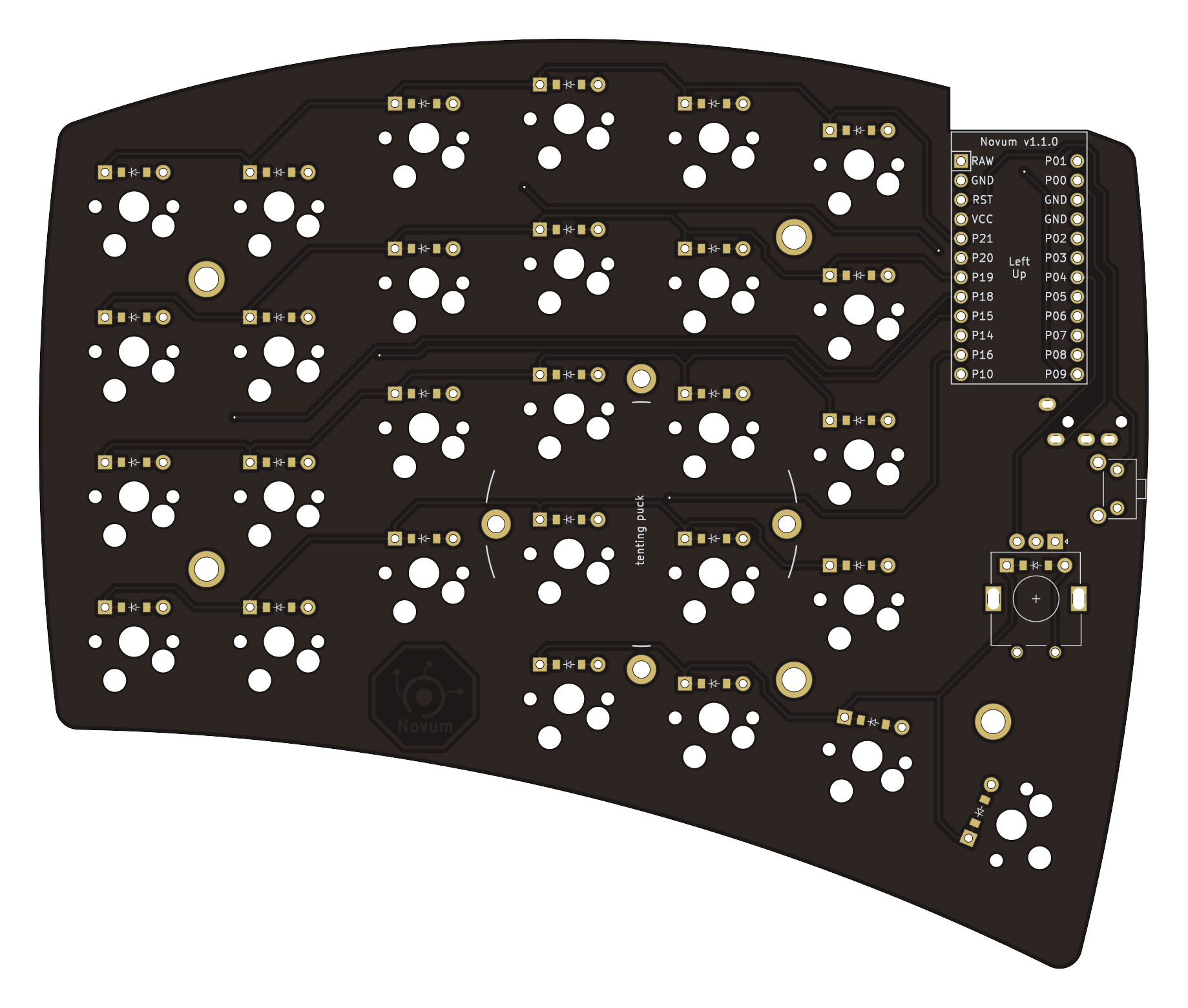 The left PCB.
In addition to PCBs, the keyboard needs a firmware, and Novum supports both
Vial and
QMK. (However, the support is not still
merged into the main repos.) I went the extra mile here, and created the
script
which generates the QMK matrix from the KiCad PCB files. So, for example, the
physical switches will always be in the right place in Vial GUI.
All of the above is wrapped into a GitHub Action, which builds all necessary
files and either creates an automatic release or posts the generated artifact in
the PR's conversation.
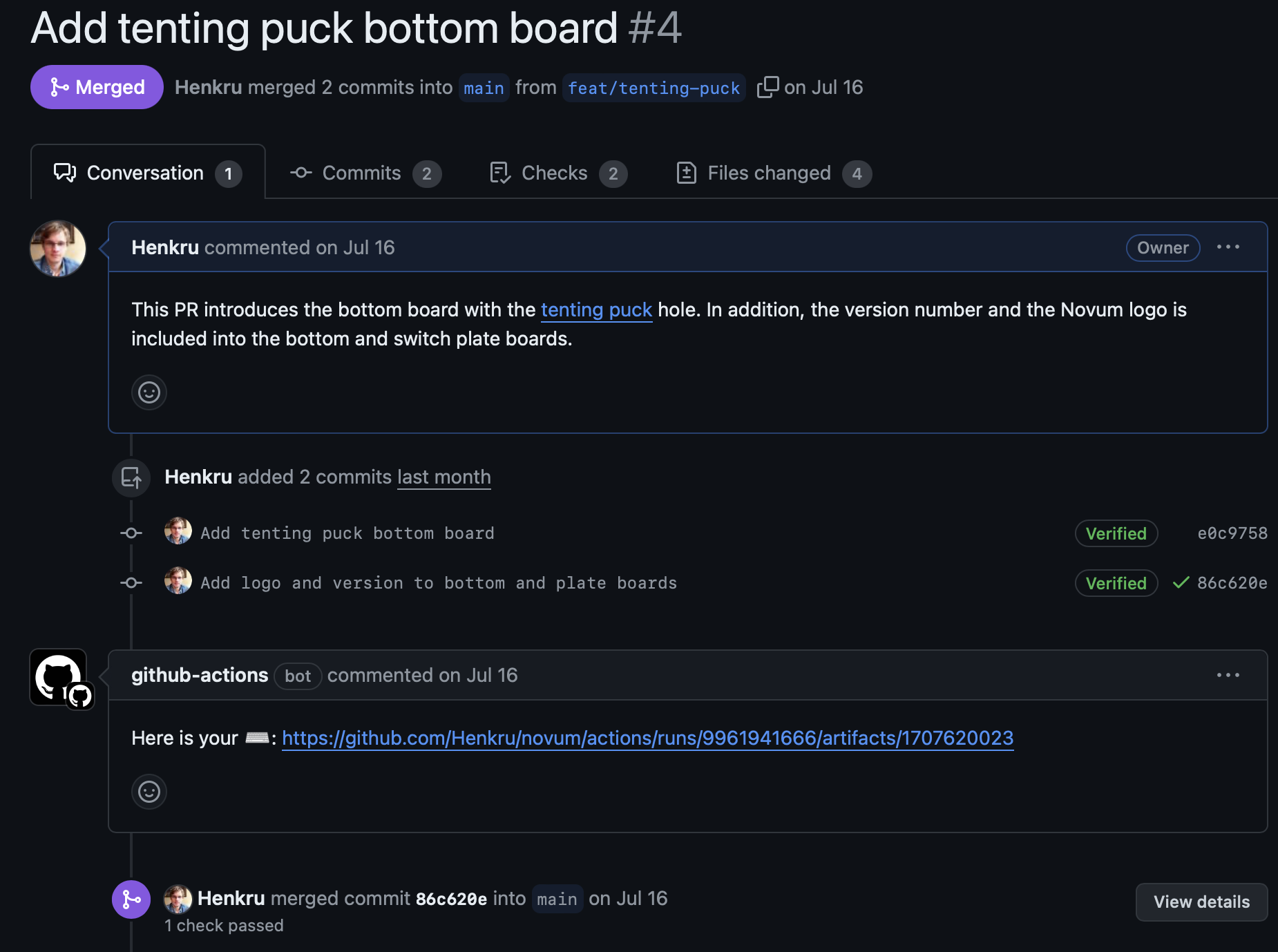 Is it
possible to over-engineering your keyboard build process?
You might ask why go through all this trouble. The main reason was to ensure
that all changes were propagated across all PCBs, and this actually saved me
multiple times. There were several moments when I wanted to make small
adjustments to edges, offsets, etc. Besides, you have to admit, it is also
super cool.
Bottom Boards Everywhere
The parametric design also allows for easily generating different options, and I
took advantage of this to create three separate bottom board designs. The first
one is just a plain board with the correct mounting holes. The purpose for this
board was just to be a backup if JLCPCB had refused the design shown below.
PCB art may be a niche art
form, but I find it fascinating to see the kind of art pieces you can create
with the extreme precision of industrial PCB manufacturing processes. So, I
decided to try my luck with JLCPCB and went All In with exposed solder mask
art on both sides for the second bottom board. I encountered a small problem
with the order form, as it couldn't produce a preview image, which prevented me
from adding the PCB to the cart. However, the design was successfully uploaded
to My Files, and after a few minutes, the preview was generated, allowing me
to order the board.
The third bottom board is a plain board with a hole for splitkb's
tenting puck. This provides an
elegant way to add tilt support to the keyboard. While I don't currently tilt my
keyboard, I figured that adding support for it doesn't cost much extra, so it
was worth including.
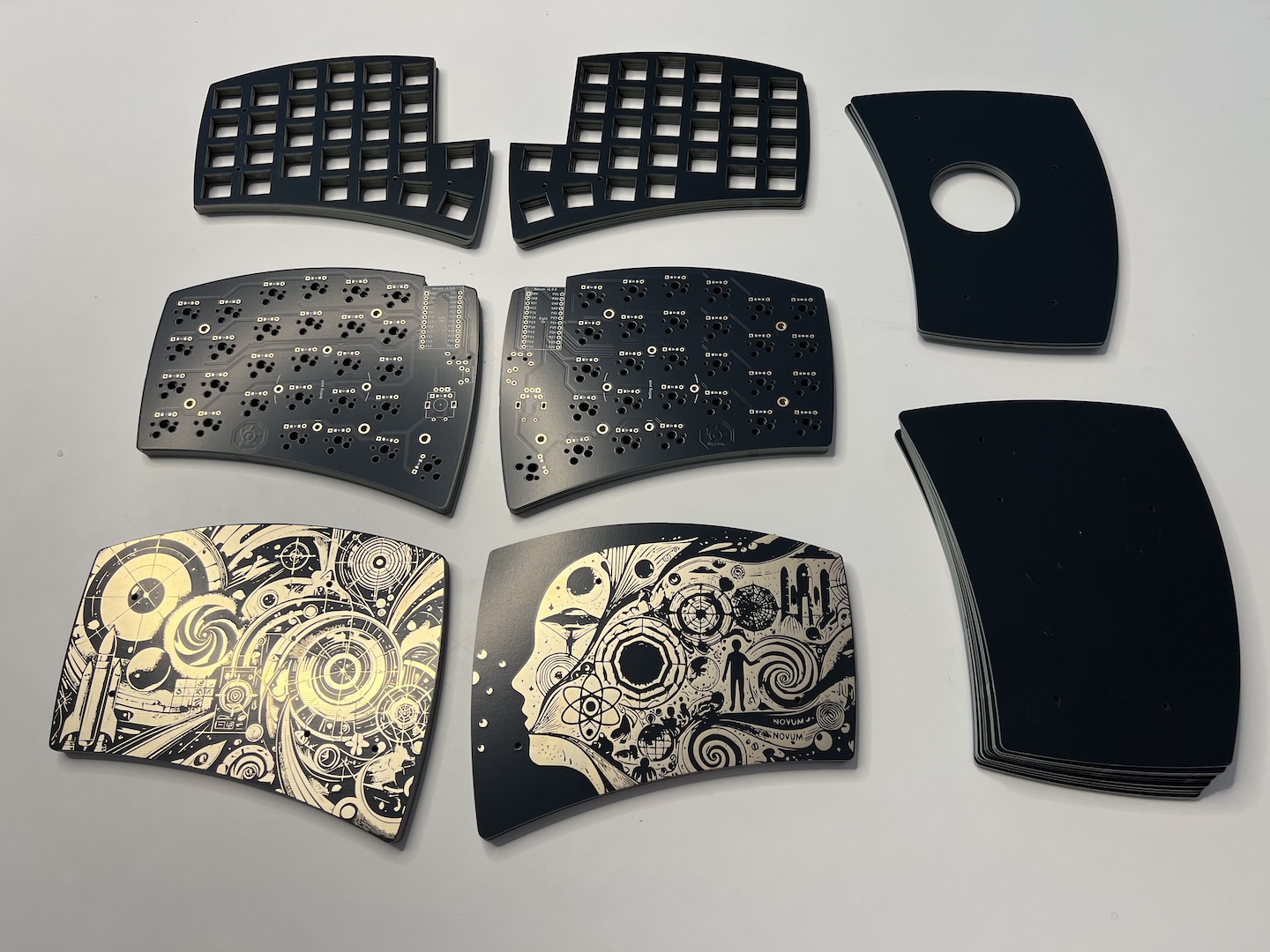 The ordered PCBs
The Result
There isn't much to say about building the keyboard, as it's a very typical
build process. Since Novum doesn't have LEDs or other unnecessary components,
I'd even say it's simpler to build than most common keyboards. This build has
GAZZEW Boba U4
Silent Tactile (62 g) switches, and
linear
encoders. I re-used the Matt3o /dev/tty
keycaps and cables from
my old Lily58 build. So, here are pictures of the final result.
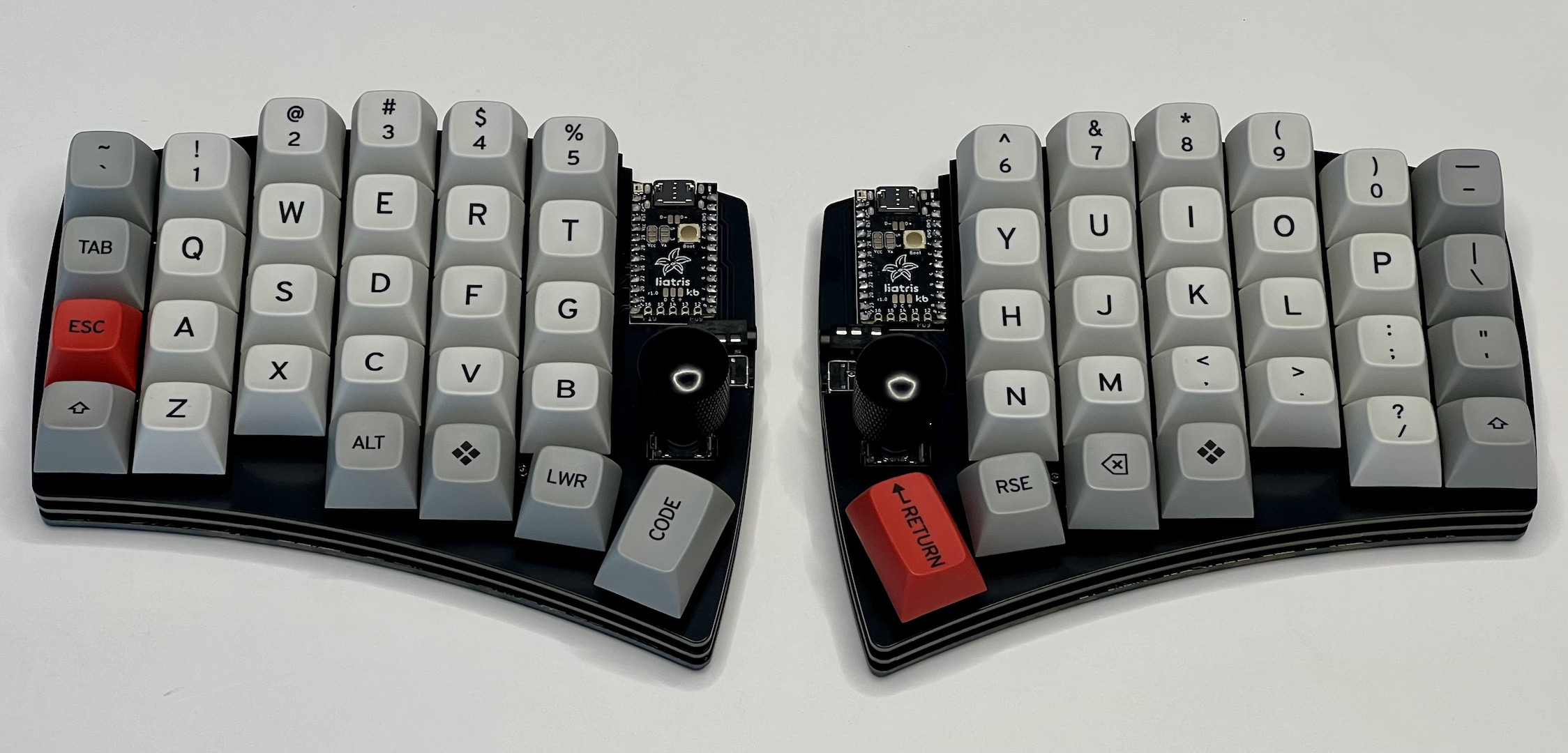 The Novum keyboard (Serial No. 0).
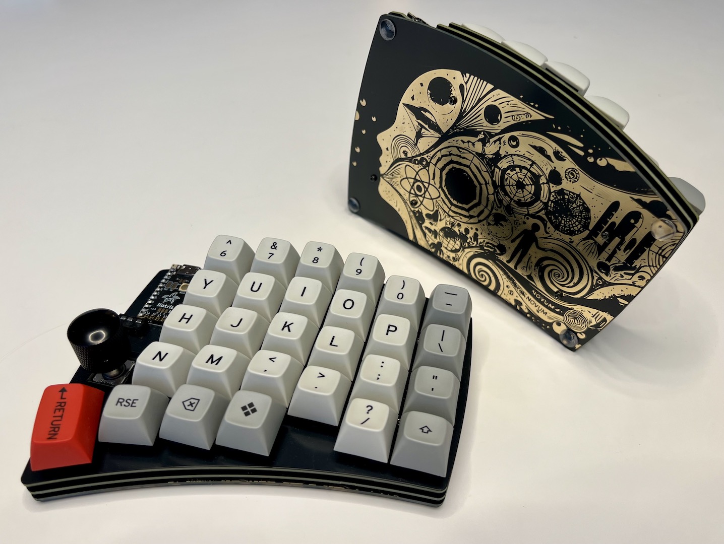 The side look.
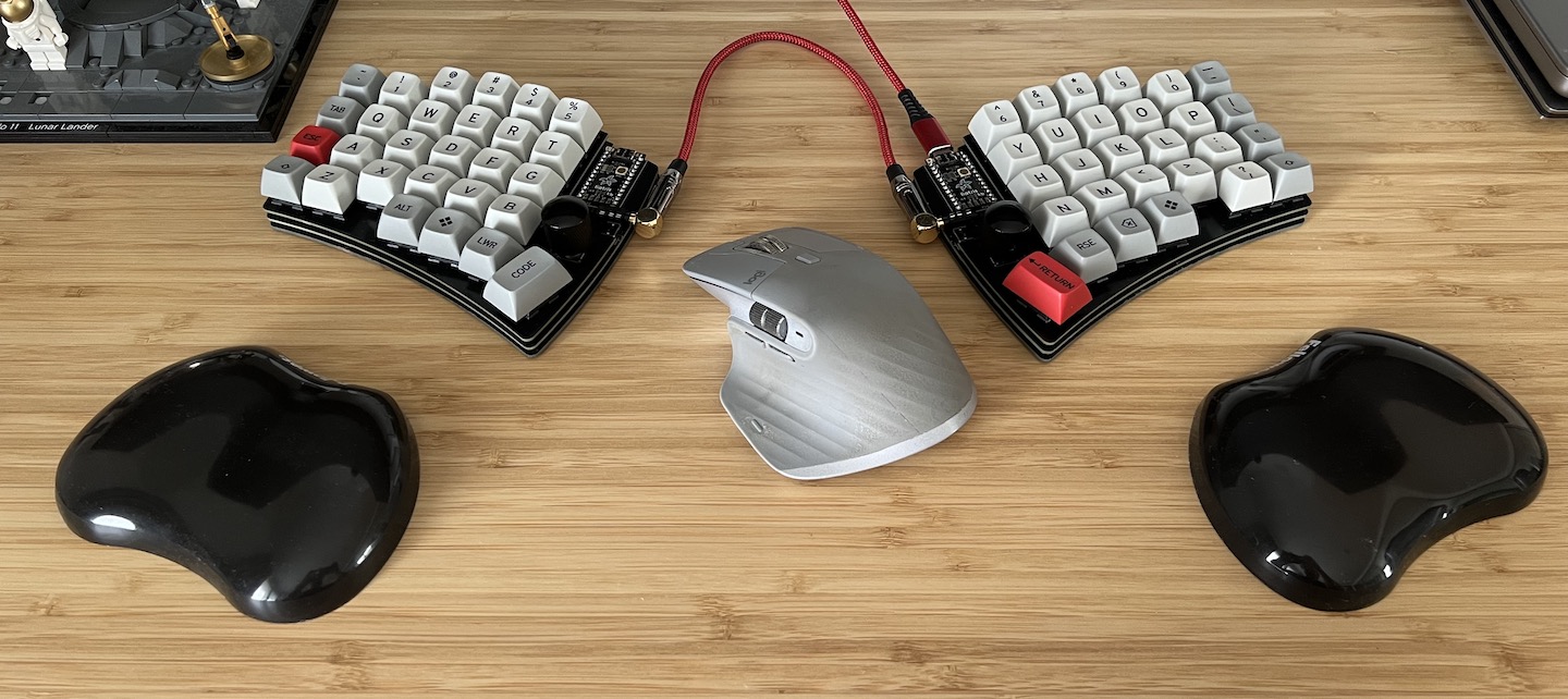 The keyboard in its natural
environment.
Final Thoughts
I'm happy with the result, and after a month of use, the layout feels very
natural — the switches are precisely where they should be :). Does this make
sense beyond being a hobby? Definitely not. But did I enjoy the process?
Absolutely.
The obvious next step is creating a proper case for the keyboard. However, I
still want to use the keyboard a bit longer before committing to a case. If I
decide to adjust the design (do I really need the number row?), it's cheaper to
order new PCBs rather than both PCBs and a case :D.
If you're interested and want to take a more in-depth look, check out the GitHub
repository.